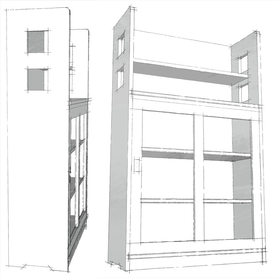
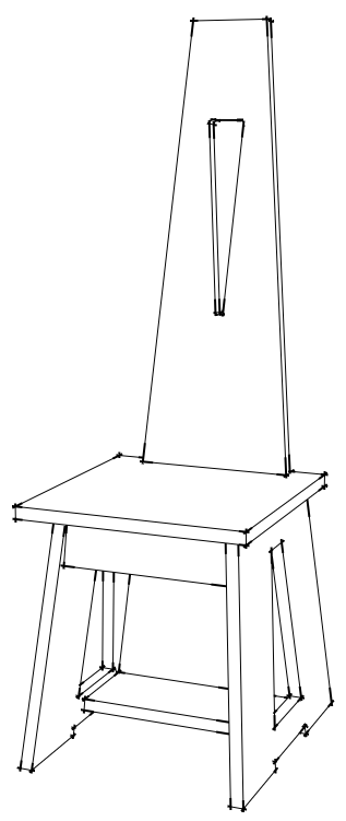
The No. 81 Hall Chair.
The original design was executed in quartersawn white oak. Because I wasn’t sure I wanted to keep the chair, I chose common pine to create a prototype. Building the prototype afforded the opportunity to verify my drawings and practice construction, then live with the chair for a while before deciding whether I liked it enough to build a final copy in another wood.
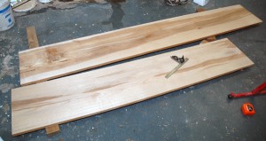
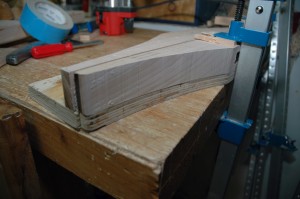
Construction began with gluing up the blanks that would form the seat, sides, and back. The notch at back of the seat is beveled to match the slope of the chair back and to fit the back’s sloping sides. I could have cut things square using a jigsaw or bandsaw, then beveled the notch with chisel and block plane. Instead, I assembled the blank from three pieces, two narrow ones surrounding a middle piece sized to the width of the back where it met the seat. I cut a bevel on that middle piece before assembly, then glued up the blank. While the blanks dried, I cut the apron and stretcher to size.
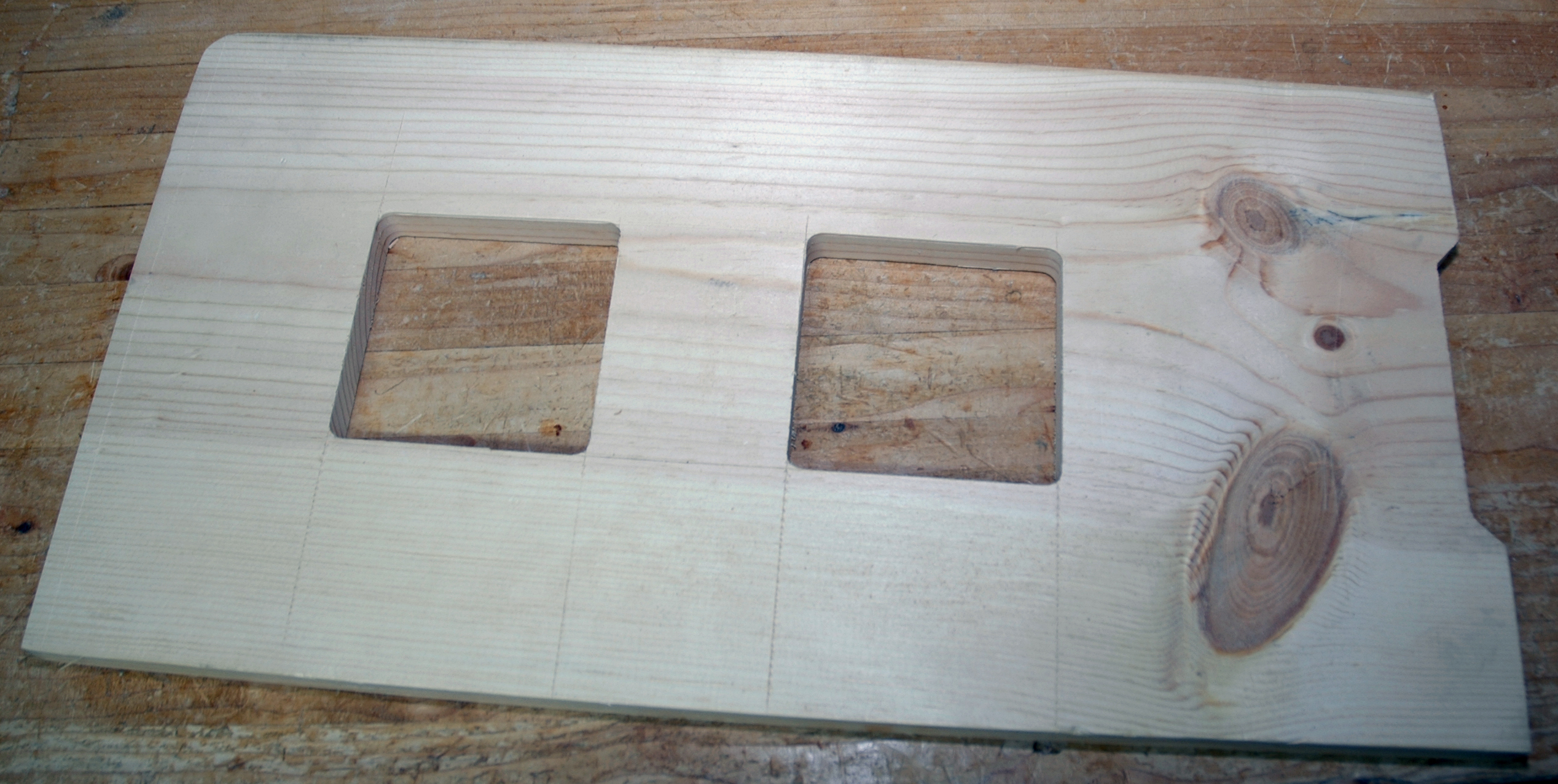
With the blanks out of the clamps, I laid out the shape of the back and cut close to my layout lines on the bandsaw, then planed things to final size with my No. 7 jointer. To produce the cutout, I drilled out the radiused corners and sawed out the waste with a jigsaw. That approach left a lot of cleanup with rasp and block plane. In retrospect, it would have been a lot easier to throw together a quick template to guide a router.
And that’s the approach I took for the cutouts on the sides after cutting the blanks to final size. The ends need to be beveled to 5 degrees to create the appropriate slope, which I cut on with the table saw set to the appropriate angle. The notch on the base was cut on the bandsaw. After roughing out the cutouts, I attached my template (four pieces of scrap held together with pocket screws), and routed the final shape of the cutouts.
Since I was using a pretty nondescript board, I decided on a finish of black milk paint. I sanded to 180 grit then used a foam roller to apply three coats, lightly sanding with 220 between the first and second coats to remove raised grain. Once the paint was dry, I was ready for assembly.
Like much of Limbert’s slab-sided furniture, the No. 81 was probably dowelled together. Dowels offered an economical way to join angled pieces together in a production environment. For the prototype, I used pocket hole screws. It’s a less-than-ideal joint for something like a chair that can see a lot of abuse, but they let me get the prototype together quickly. I drilled my holes, clamped the sides to the aprons using angled clamping blocks, and screwed the base together. Then I attached the seat followed by the back. On the original chair, the back was screwed to the edge of the seat and to the bottom stretcher and the screw holes plugged with oak buttons. I screwed the back on and plugged the holes, then cut the plugs flush. After some touch up paint around the plugs, I wiped on a couple of coats of boiled linseed oil and some dark paste wax.
The finished chair seems smaller in person, slightly unassuming for such an iconic design. And it’s not especially comfortable (I sometimes cynically wonder if that is intentional, a design meant to hurry guests in or out of the entry way). Rendered in black and divorced from the quartersawn white oak that characterized most Arts & Crafts furniture, it also seems curiously timeless. The lack of color highlights the accomplished use of positive and negative space and the dynamic intersection of angles. In fumed oak, it’s at place in the Arts & Crafts home, but done in maple or teak and it could pass for Danish modern. In black or white, it could pass in an industrial loft. I still haven’t decided if I’ll do a final copy, and if I do, it will be hard to choose what wood and finish to use to give it its character.